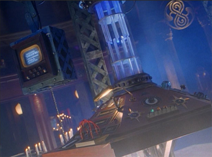
This is the single most complex template I have ever built. Special thanks to Smappy and Jeffrey Fink, whose original designs I mashed thegether and then built over the top of to form my own version. Also thanks to Brian Uiga, who restored the original 1996 prop, and sent me an astonishing number of up-close photos, that were invaluable for creating an accurate miniature version of this masterpiece.
Make sure you read this parts list very carefully before you start printing and realize partway through that you don't have all the bits you need. This template requires several
of the internal column pieces be printed out of resin. They are far too small and delicate to print out of transparent PLA or PETG. If you do not have a resin printer, you will need to use a 3D printing service or find someone who can print these parts for you. Additionally, several off-the shelf components are needed for full assembly.
To complete this playset, you will need:
1 x clear acrylic tube, 22mm outer diameter, 2mm thick, 18mm internal diameter for the central column. (Hard to find except on eBay shipped from China. You can also print one yourself out of clear resin, but it may not be as perfectly transparent as buying a pre-manufactered one.)
1 x 40mm tall, 16mm wide compression spring, for the upper half of the central column. (Note, if you don't use one, the time rotor will always be in the lowest position. If shopping online, make sure you get the ones that look like normal metal coil springs. Do not buy anything that's color coded with thick flat coils or that says "Die Spring" in the description as these are used in die stamping machines, and are far too rigid to use inside a plastic toy)
OPTIONAL 1 or 2 clear acrylic rods, 1.5mm outer diameter, to be cut to length for the internal tubes of the central column if you are not printing in resin.
15 x M2 x 5mmhex bolts, with locking nuts (14 for monitor arm, 1 for hand crank)
4 x M2 x 10mmhex bolts, with locking nuts (2 for top and bottom of monitor arm, 1 for handbrake, 1 for demat lever)
1 x 1.5mm wide brass rod (to be cut to length for axels of destination cylinders)
OPTIONAL 1 x
white 2x3 LED Light-Up Brick NOTE: This needs to be the type with the Lego axel-shaped hole that can be pushed in to function as a button, NOT the slide switch type.
OPTIONAL 1 set of 30 or 40 LED white LED string lights (Must be the type that takes CR2032 batteries and has a switch at the base) for the bottom of the console and internal lights.
OPTIONAL 1 set of 10 LED white LED string lights (CR2032 battery, switch style) for the top half of the console. Note: Check on eBay, as it is getting increasingly hard to find the shorter length LED string lights. In this case, you want as few LEDs as possible to only illuminate the top of the column and the 6 spotlights. You can go with a 20 LED string light in a pinch, but you may have to wrap the end of the string in tin foil to prevent light leakage. If you don't plan on using the upper spotlights, you can illuminate the column from below only, but it won't be as bright or look as good.
OPTIONAL Heavy duty tin foil for wrapping unneeded LEDs and to block light leakage.
1 bottle of clear UV craft resin for the spotlights and other light-up console elements. The thicker stuff is best.
1 pack of liquid UV Resin coloring dye in assorted colors, for creating different colored lights for the console. (I've heard of some people using regular food coloring, but it's not that expensive, and you'll only use a few drops at a time)
1 multipack of blunt tip 18GA or 20GA dispensing needles and 1ml syringes (the kind used for jewelry and refilling vaping pens) for controlled delivery of the clear resin and resin dye. You will want at least 6. These are disposable, and each color of resin should go in a different syringe. Do not mix and match colors because it is impossible to clean them out afterwards and the syringes will eventually clog once the remaining resin inside sets up.
90% or higher Isoproply Alcohol and paper towels, for wiping down the destination cylinders after painting. (This is the best way to get the text to show up if resin printing. If you're printing the blank cylinders and using stickers, you can skip this part and the paint pen.)
Nitrate gloves (to protect your hands from the resin), some small epoxy resin mixing cups, or cheap disposable plastic paint palets for mixing and syringing up the colored resin and an airbrush (highly recommended) for painting the large and highly detailed parts.
Print and assembly is a very complicated process and there are multiple file options depending on whether you are printing in resin, filament, or both.
I have split up the STL files into two main subfolders; SLA Resin Printing and PLA filament printing. The PLA folder then has an additional subfolder of Small or transparent parts recommended for Resin which contains the higher quality resin versions of files. While I have tried to include PLA or PETG friendly versions of all files, some of the really small parts just weren't build for that level of detail and may just not work.
There are
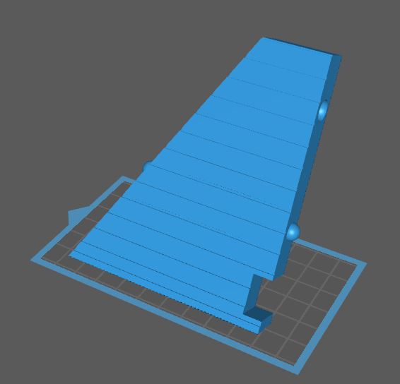
multiple versions of the base plate files in the SLA Resin Printing directory. Unless you have a truly massive resin printer like a Moai or Transform, you will need to print the Left, Right and Center for SLA versions which are designed to fit on a normal sized Photon or Elegoo Mars print area, as long as you angle them.
Pay attention to how many copies of each part it tells you to print. Each of the Arch pieces will need to be printed 6 times. You'll also need to print 1Base Plate center, 6 Base Plate L, and depending on whether you want to include LEDs, 5 Base Plate R + 1 Base Plate R with LED Hole, or 6 Base Plate R for a solid unlit version.
Before painting, it is recommended that you fit all parts loosely together without glue to make sure that they fit and move freely. You may need to sand down some parts or drill out some holes if they are too tight or don't fit together smoothly.
This is more or less the order of how I assembled mine. You can do some of the steps out of order, but be extra careful before you start glueing anything together.
1) Print all your pieces.
2) It is now safe to glue together and paint the 6 Arch Top/Middle/Base pieces and clawfoot console base and middle. Since they are all the same color, you can also use this opportunity to paint (but don't glue) the Upper Central Column pieces, the Central Column Base Ring, and all the metallic parts of the Scanner except the Wooden Scanner Face and Clear Scanner Screen.
3) Paint the wooden scanner face, then fully assemble the scanner with the LED brick, if you intend to use one. You can use the video below as a guide.
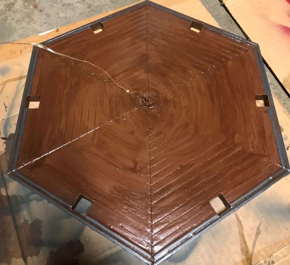
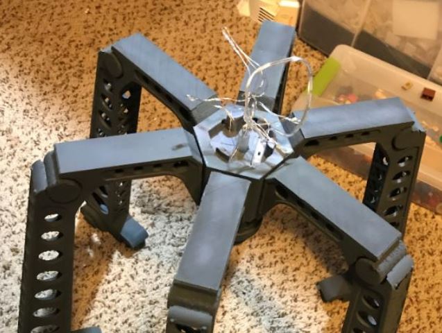
4) Assemble and paint the 6 triangles that make up the base plate. If you are using the LED string lights, either glue the LED battery pack in place, or make sure you have enough room to string it up through the hole on the center of the hexagon. Depending on how wobbly the tips of the triangles printed, you may need to drill out or otherwise widen the hole.
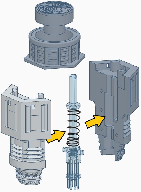
5) Slot the top of the 40mm tallcompression spring over the top of the Clear or Solid upper central column spring rod, and then screw the spring rod into the top half of the time rotor. You will then need to slot the spring assembly inside the two halves of the painted Upper Cental Column. (Note, you may need to sand down or snip the corners of the 4 pegs on the upper time rotor to get them to slot into the grooves)
Once you are sure everything fits snuggly, carefully glue the two halves of the Upper Central Column together (don't get any clue on the spring or internal time rotor mechanism), and then wrap tightly with a rubber band.
If you are going to use LED lights, drip a single drop of blue-tinted UV resin down the hole into the end of the cental column spring rod. This will give the console it's distinctive blue light look. Tap the liquid resin down to the end with a long bamboo skewer or a spare brass rod, so it's not sticking to the sides when you shine the UV light in to try to cure it.
Once that's done, you can stick a LED down the hole if you want to test the color, but don't glue it in place yet.
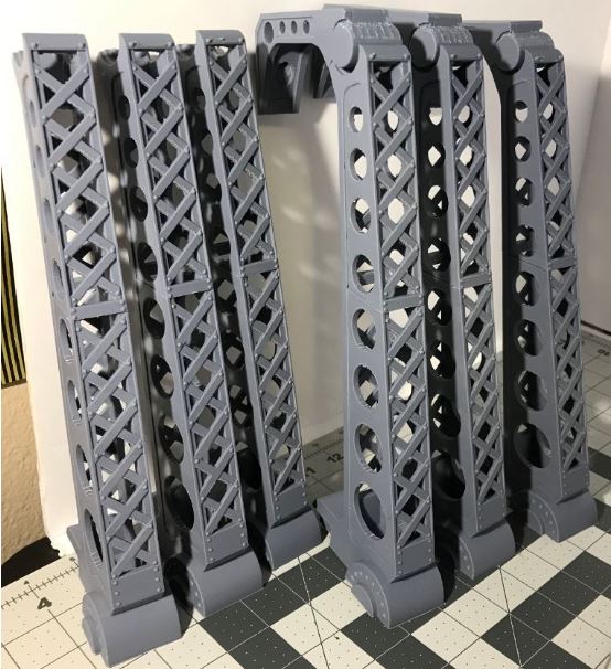
6) After this has had a chance to dry, confirm the spring mechanism works as intended. Once that's done, you can glue the 6 Arches into the slots on the outside of the upper central column.
If you are doing LEDs for the upper half of the console, slot the battery pack into the rectangular slot with the switch facing upwards. DO NOT glue it in place, as you may need to change the batteries at some point in the future. Beginning with LED closest to the battery pack, string one LED out through the small holes along the upper perimeter of the central column into the holes in the arches that lead to the spotlights. Make sure they poke out far enough that you can easily manipulate them when the columns are glued in place.
If you cannot find a short 10 LED light string, you will have to make due with a 20 and wrap the LEDs 7 through 17 in tin foil toblock their light. If you have extra LEDs, DO NOT CUT THE END OFF YOUR LED STRING LIGHT!!!! Doing so changes the total voltage and will cause them to overheat, and burn out faster, assuming they don't catch fire and/or burn down your carefully crafted model. The last two or 3 LEDs on the string should be crammed down the hole in the central column spring rod as close to the bottom as you can get them. (Use the same bamboo skewer or brass rod to push them down.)
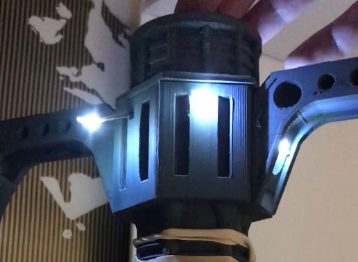
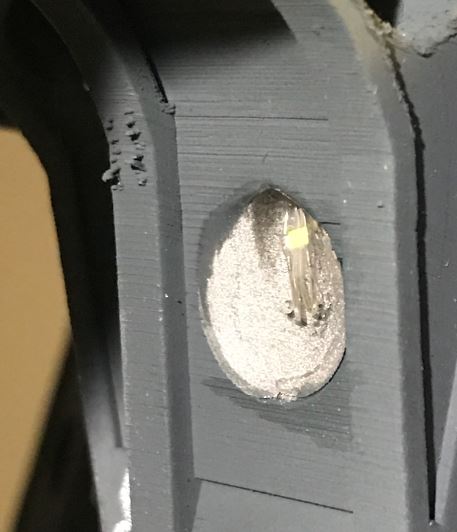
7) Once the arches are in place, push and bend the LEDs so that they are just barely visible from within the circular depression at the top of the arch. I painted the interior of these spotlights reflective silver on my model, but it didn't make a shred of difference, so I wouldn't bother on yours. Once the LED is visible, but not sticking out too far, begin filling the depression with clear UV resin from a bottle, tube, or syringe. I recommend just barely covering the LED at first, then curing that layer with about 30-60 seconds of explosure from a UV flashlight to lock it in place. Once the LED's not going anywhere, tilt the arch so that the front of the spoitlight is perfectly level, and then pour just enough resin so you get a nice smooth slightly curved dome of resin. If anything spills, wipe it up quickly with a paper towel before you cure anything. Repeat this process for all 6 spotlights.
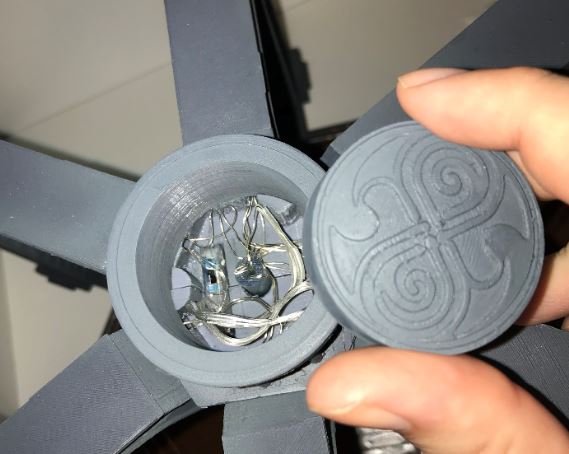
8) Try to flatten the wires down as much as possible, leaving both the tip of the spring rod and the switch for the LEDs accessible. You can now glue down the top Button Housing collar, unless you decided to print the Alternate Flat Plate (if vertical shelf space is an issue).
If you're using LEDs, DO NOT glue down the Flat Plate or Circular Button, as this needs to be removable to access the LED switch.
9) That does it for the upper half of the console. On to the bottom half.
If you want, you can glue together Console Panel Segments 1-3, and 5-6, but make sure they line up straight, otherwise you can end up with a crooked console or a big gap when you eventually glue all 6 parts together. Panel 4 must remain separate until the very end.
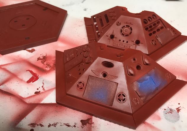
Next, give the 6 console top pieces and the underside of the Console a good base coat of rust/brown/red paint, as close as you can get to the mahogany color shown in the Color Recommendation section. It is a good idea to use an airbrush here and to masking tape off all the control panels that need to be a metallic color. Don't forget that you also need to paint the underside of the wooden shelf edge of the console too.
Once dry, you can lightly dry brush horisontal streaks with a
dark brown color to create the wood grain lines. Let this dry, then apply a second coat of the rusty mahogany color.
10) Now, paint all the individual control panel elements. Consult the Color Recommendations and video below for tips.
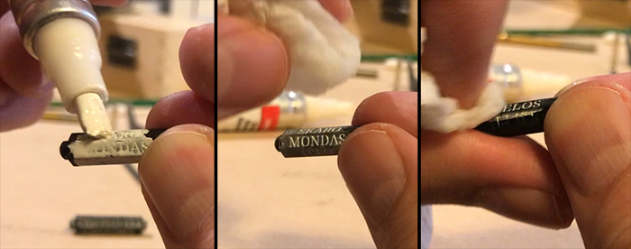
11) If you resin printed the black Destination Cylinders, paint over the text with a white Testor's paint pen, then wipe off horizontally with a paper towel soaked in Isopropyl Alcohol, as shown below. If you're using stickers... move along to the next step.
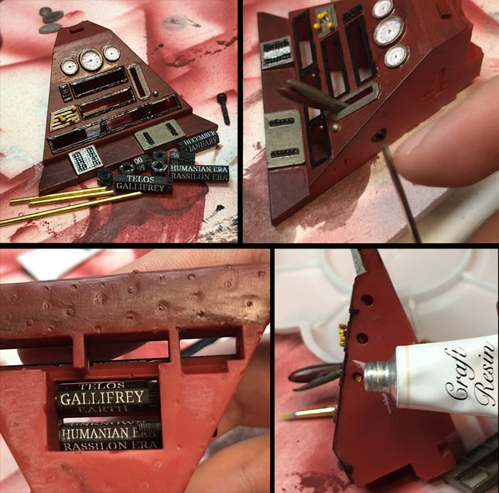
12) Once the cylinders are painted, it's time to mount them in panel 4.
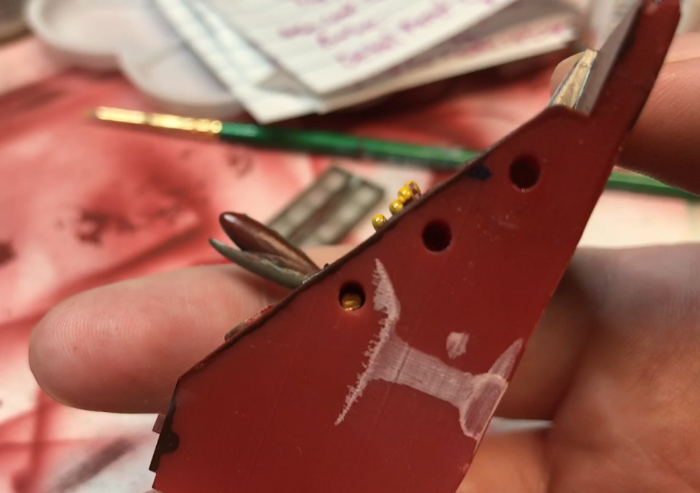
First, take your 1.5mm wide brass rod and stick it into one of the three holes on the left side of panel 4. Mark the point where it sticks out with a sharpie and then cut slightly shorter than where you marked. Repeat with the other two holes. The goal is to have three rod lengths that fit snuggly in the holes without sticking out past the edge.
13) Once you have your 3 rod lengths, set them aside for a moment and use a long M2 x 10mmhex bolt to secure the hand break (the smaller metal handle part of the lever should be on the top) through the hole on the right side of panel 4. If the head of the hex bolt sticks out slightly past the edge, you may have to use a drill or dremel on the corresponding corner of panel 5 so that the two can sit flush together for assembly.
Next, take your desitination cylinders and begin placing them in the slots from the underside of the console. Then thread the brass rod through the middle so that they spin freely like a bead on an abacus. (Also make sure that when you flip the console panel back over, the text is displaying in the correct direction.) If the destination cylinders don't spin freely, check for minor print defects, overhang supports that didn't get removed or something else that may be blocking their movement.
Once you are satisfied they spin correctly, take a tiny blob of UV resin, and cement the end of the rod in place. Repeat with the other two rows. (The bottom row is the hardest, since there are multiple cylinders that must be lined up exactly. It's easiest to start from the closest edge, dropping the pieces in with a pair of tweezers, and then pushing the rod through as you go.)
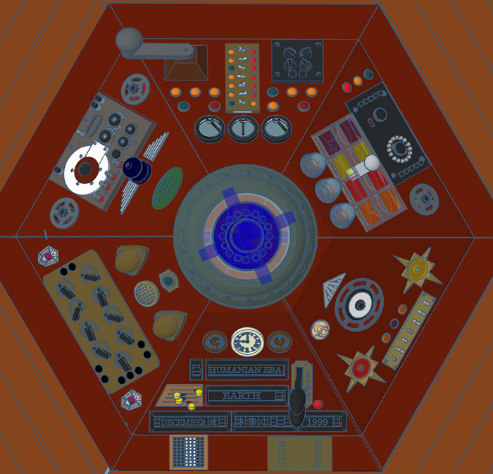
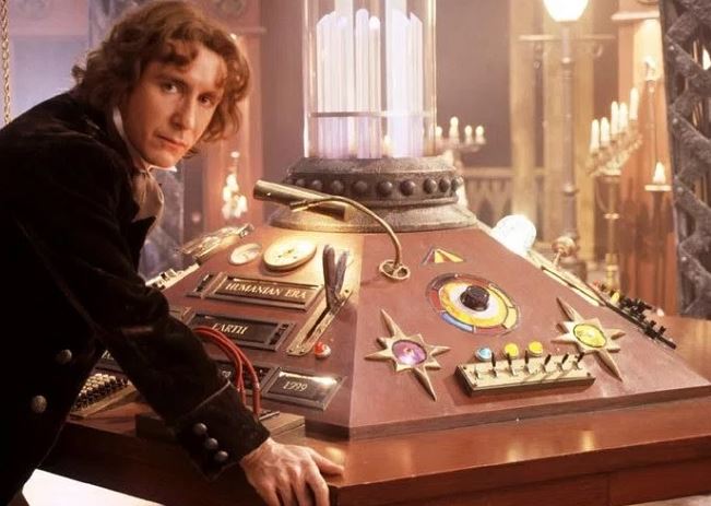
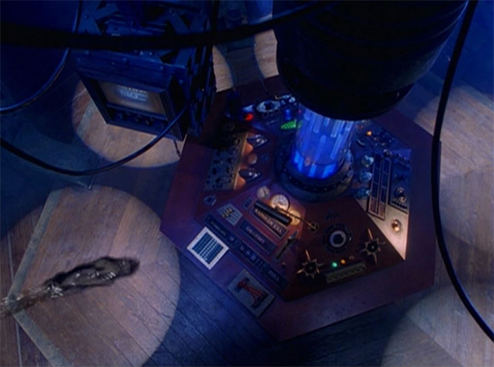
The diagram below will give you an approximate guide for general color and light positions.
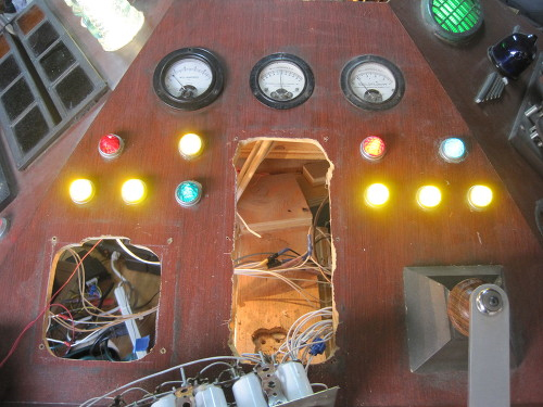
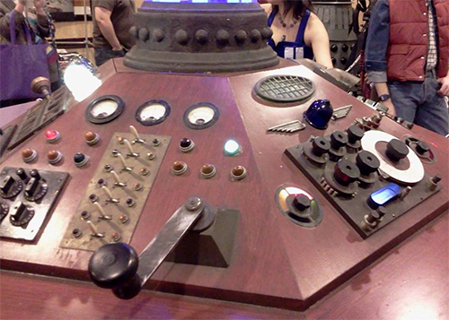
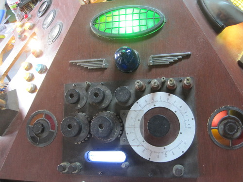
And here are closer panel-by-panel views of the console.
Pre-Restored Panel 1
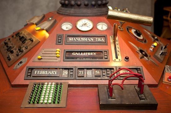
Restored Panel 1 and 2
Pre-Restored panel 2
Pre-Restored Panel 3
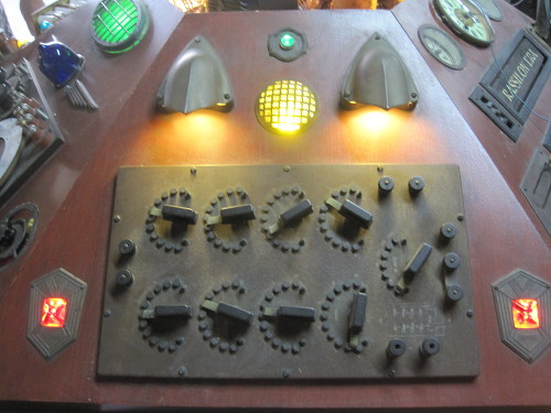
Restored Panel 4
Original Panel 4 and 5
Pre-Restored Panel 5 (note order of botton lights is off. It should be Blue, Yellow, Yellow.)
Pre-Restored Panel 6
Scanner and Time Rotor. Note that the rotor should be transparent opaque white. It's only the top and bottom lighting effect that makes it look blue.
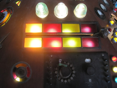
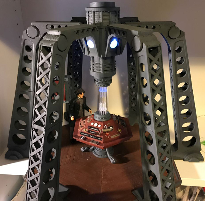
Below you can see the spotlight placement and that the outer edge of the wood platform is a lighter grey color, similat to that of the columns.
Designs featured on this page are protected under Creative Commons License CC BY-NC-SA (Attribution-NonCommercial-ShareAlike) and will only remain available as long as licensed versions of the figures do not exist. All files, including all future releases will stop being shared if *ANYONE* is discovered attempting to produce and sell figures based on these designs for financial gain.
If you aren't sure what this means, read the F.A.Q. page, or just assume that if you are requesting money in exchange for products printed using these templates, you are breaking the project rules and DON'T DO IT!
Doctor Who and all related IP rights belong to the BBC. This is a not-for-profit fan site for personal entertainment purposes only.
No copyright infringement intended.