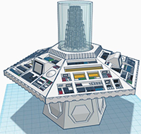
020 - 20th Anniversary TARDIS Console
From The Five Doctors (1983)
Version 5 - Updated 3/3/2019
Beta: https://drive.google.com/open?id=16gSV4SxGoi-iYr8jckHYzYURetYRuVPs

Special thanks to Peacock Pete on Thingiverse, who's console formed the basic skeleton of my design.
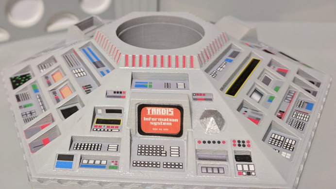
I held off making a TARDIS console for a full year, because I knew it would have to be spectacular, and I wanted to be at the top of my game when I created it. The design you see before you is as screen accurate as physically possible, even down to placement and colorization of the individual buttons. This is a VERY large figure that will just barely fit on my 7.9" x 7.9" x 7.1" build area if I disable both Raft and Brim in CURA. I have included manual brims as part of the PLA version of this figure to try to prevent curling on the outer corners, which is especially problematic for this piece in particular. Please verify your printer is large enough to handle it before you attempt to print. As of Version 5, this design also has support for a single 20 LED Fairy String Light that can be used to light the various console displays. (Note: some of the photos below show the earlier 4 version which used two multi-colored LED string lights. This is actually less screen accurate than just using white ones, and takes up more room, so I changed it)
I'm still listing this one as a beta design since I plan to release an even more improved version with a motorized central column that's fully parted out for SLA resin printing.

It is absolutely *ESSENTIAL* that the upper and lower halves of the console come out perfectly flat with no curling. If you have a heated bed, I recommend investing in an Anycubic Ultrabase borosilicate plate of the appropriate size for your build platform. Jack the bed temperature up to 70 or 80, spray a bunch of non-aerosol hairspray before and during printing of the first layer, and seal the entire printer in a cardboard box if you don't have an enclosed build area. Anything to keep the heat consistent and the corners from curling.
This is one of my most complex designs and comes with several variant pieces depending on how you intend to print it:
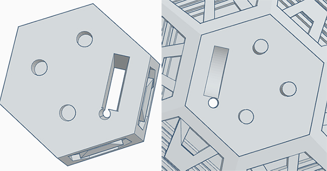
- There is an alternate Blank Console Top that contains no buttons, for people who want to add them in manually using some other method. Everett Bailey designed a very cool sticker set (see photo above) specifically for this model that will save you a bunch of time if you don't want to do a bunch of detail painting. Otherwise, use the "Grey console top (with buttons)" STL file for the full 3D experience.
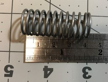
- You also have the option of using a 1½" by 5/8" compression spring (40mm x 16mm) to make the central column rise and fall when you press down on it. If you don't use a spring, it will default to the lowest position. You can still move it by pulling up on it, but you'll be pulling against the glue holding the time rotor in place and it may break lose if played with too forcefully.
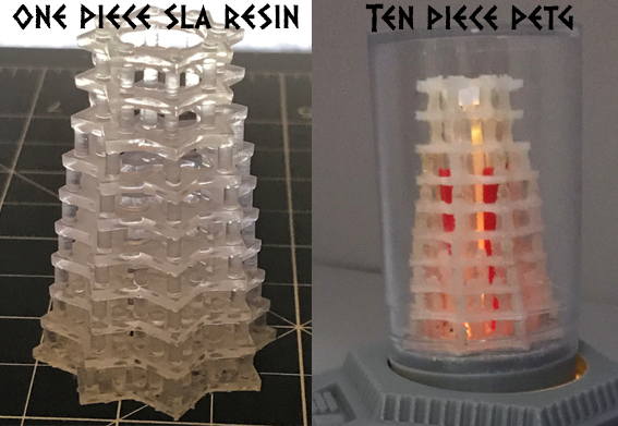
- There are two separate folders for the central column's transparent pieces. There's a Column interior glass (solid for SLA printers) version where all 10 layers of the column interior are attached together that can be used if you have access to a SLA resin printer that can print it all nice and clean without blobby artifacts. Everyone else will need to use the "separate column layers"
folder to print all 10 layers of the column separately in transparent PETG or PLA, which will then need to be cleaned up and glued together.
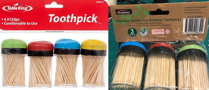
- I have included a printable version of the outer column exterior glass shell, but unless you've got a SLA printer, it's not going to print clear enough to see through, even if you use PETG. Instead you will probably want to use something else that's 40mm wide and then cut it to the appropriate height. You can order clear acrylic 40mm tubes on eBay or from your local plastic supplier, or for a super cheap alternative, pick up one of the generic multi-colored toothpick dispensers below (packaging appears to vary depending on where you live, but you can find them in the US, UK, and Australia). They're the perfect size, but do have a slight ring around the top edge, which is annoying, but I haven't found a better alternative.
If you use 40mm acrylic tubing, I have included a 3mm tall Column Topper that you can print out of PETG to form the top that should be more or less see-through if you print it on a glass plate and don't flex it before it's had a chance to cool.
Note that due to the incredibly small size of the column's internal pillars, if you try to print with PLA or PETG, it's going to come out looking like crap, even with separate layers and a HD printer printing at the slowest print speed possible (I printed mine at 4). You're going to have to do a ton of cleanup work with an xacto blade and soldering gun to make it look even halfway decent before gluing all the pieces together. But before you glue...
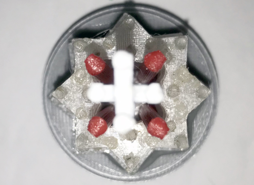
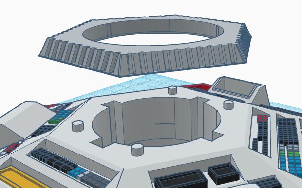
Make sure all 10 pieces of the central column are lined up in the correct sequence largest to smallest, and take note of the orientation of the four circular indentations. These need to be lined up vertically so that the red interior tubes will have room to slot into place. You will want to glue the first five layers together, and the last five layers together to form two large pieces, but do not join thee two halved together yet!
Once dry, attach the bottom layers of the column to the column base so that the holes line up, then insert the red column pieces into the four large holes in the column base so that the prongs go into the appropriate holes. Next, add the white column pieces inbetween them in a + pattern (see below).
The bottom five layers of column should help hold the pieces upright when you glue them in place. Once everything seems to be standing upright, you can add the top layers of column and seal the colored pieces inside.
If using a spring for your central column, you will need to glue the 1½" by 5/8" compression spring to the underside of the column base prior to assembly. These springs can be found in most hardware stores in the US, but I have no idea how common they are in the UK. Make sure you get a light duty spring that looks like the photo below. I've seen some flatter heavy duty springs on Amazon that are the correct outer dimensions, but are designed for metal stamping machines, and far too rigid to be manipulated by hand and used inside a plastic toy!
Glue the column neck down to the top of the console and let it set permanently before you attempt to insert the central column up from the underside of the console top. Make sure you glue it down well with crazy glue or another extra strong adhesive. When fully assembled, the column neck stops the spring-powered central column from popping up and out of the console. The guide tracks for the central column are 2mm shorter to the spring itself, so there will always be some slight pressure against the underside of the column neck and column base, which may pop loose if they aren't glued securely. (It is also a lot easier to paint in the red stripes on the column neck *before* you glue it down to the rest of the console)
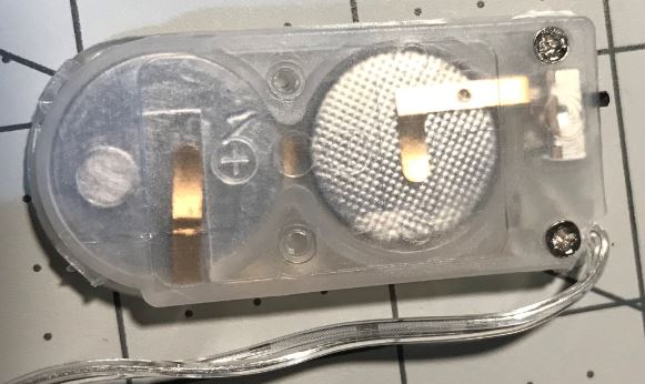
Light-up Recommendations: Note: several of the example photos below are from my first Version 4 attempt, which used multi-colored lights. All lights on the 20th Anniversary Console were white, so you should use one set of White 20-LED Fairy String Lights if you plan on making your console light up. These should be the style that uses two CR2032 lithium watch batteries, and has a switch on the end, rather than a push button.
The first thing you're going to need to do (after putting batteries in your string lights and making sure they all turn on) is clip off the very corner of the battery box by the wire so that the wire can exit from the long side rather than the side by the switch. Though you will have more LEDs than are strictly necessary *DO NOT* remove any lights off the end of the string. The voltage is calcuated for exactly 20 LEDs, so removing any will make the wires overheat and the remaining LEDs burn out faster.
Push the battery box up through the long rectangular hole in the console base, so that the light string goes up through the circular hole and through the corresponding hole on the console underside. Only the switch should be visible on the bottom of the console, but positioned deep enough that it will still lay flat. Leave yourself enough loose cordage before you start gluing down LEDs that the battery pack can be pulled out the bottom to replace batteries if needed.
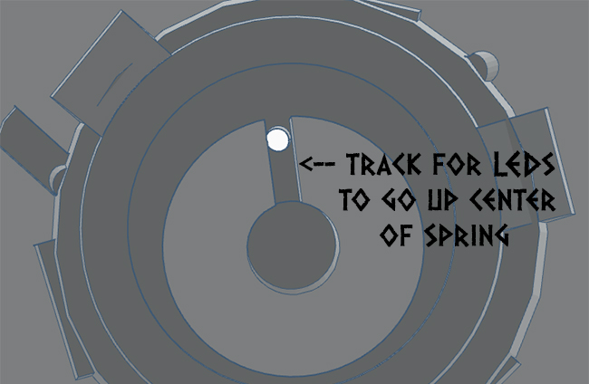
There is a shallow track by the hole to the console base leading to where the bottom of the spring sits. You will want either the start of end of your LED light string to deposit the majority of the LED lights you won't be needing for control panel elements here to light up the central column.
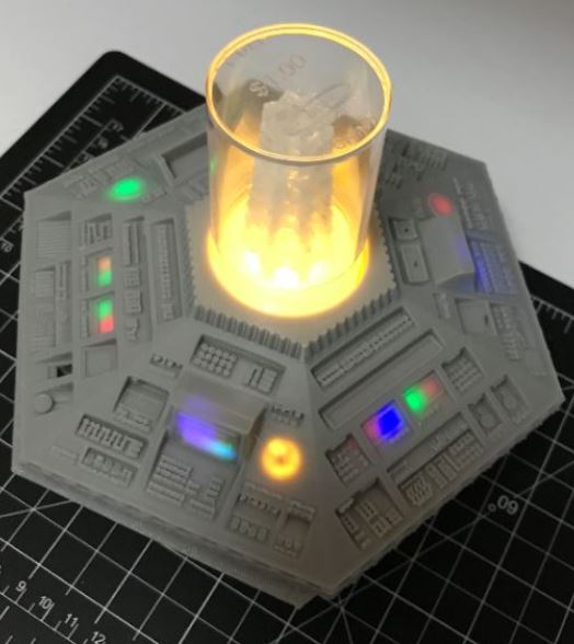
There should be enough wire between the individual LEDs that you can string the lights from one hole to another on the underside of the top of the console without leaving any LEDS hanging out in the middle of nowhere (Note: photo above is from my old multi-colored Version 4, but your lights will be white).
Placement is likely to be a matter of trial and error until you get something that looks right. Make sure the lights are switched on when you are placing them so you can judge the amount of light spillage through the surrounding plastic.
The best way to block light spillage is by gluing down small strips of tin foil along areas that you don't want the light to shine through, like the tops of the monitors. For the monitors, I made two small rectangular boxes out of tin foil that I carefully pushed inside the hole with tweezers so that light would only go out the front part of the screen. Once you have your tinfoil layers in place, reinsert the LED lights where they need to go, and then use transparent window sealant or clear UV resin with a UV flashlight to fill the holes and lock the LEDs in place.
UV resin is the preferred option if you can get it, since it dries completely clear and rock solid in less than a minute. The transparent window sealant is cheaper, but it takes a full day to dry, and does shrink a bit, so LEDs can sink or shift around if you aren't careful. The only plus side of the window sealant is that (theoretically) if you had a LED burn out, you could carefully dismantle the console and then dig the affected LED out and replace it. With the resin, it's locked in place forever, and you will never be able to touch or move it again once it's been set in place.
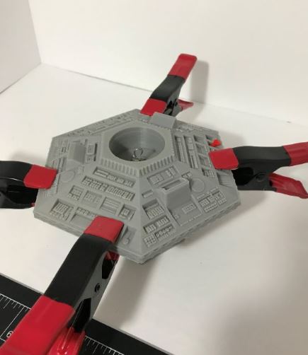
Your final tasks before gluing the top and bottom halves of the console together are to make sure the door lever, Central column, and spring are all in position and working properly. Remember to check if there's any light spillage visible through the bottom of the console as well. If there is, you can easily apply a few more layers of tinfoil.
Use E6000 or another strong gelled epoxy to glue the two halves together, making sure that the wires aren't stuck anywhere that they'll force a gap between the two pieces. Once you have the two halves perfectly flat and aligned, use at least 3 to 4 clamps to hold the two pieces together until dry.
Note: Photo below shows Version 4 where the column and spring were added later. Yours should already have the column in place.

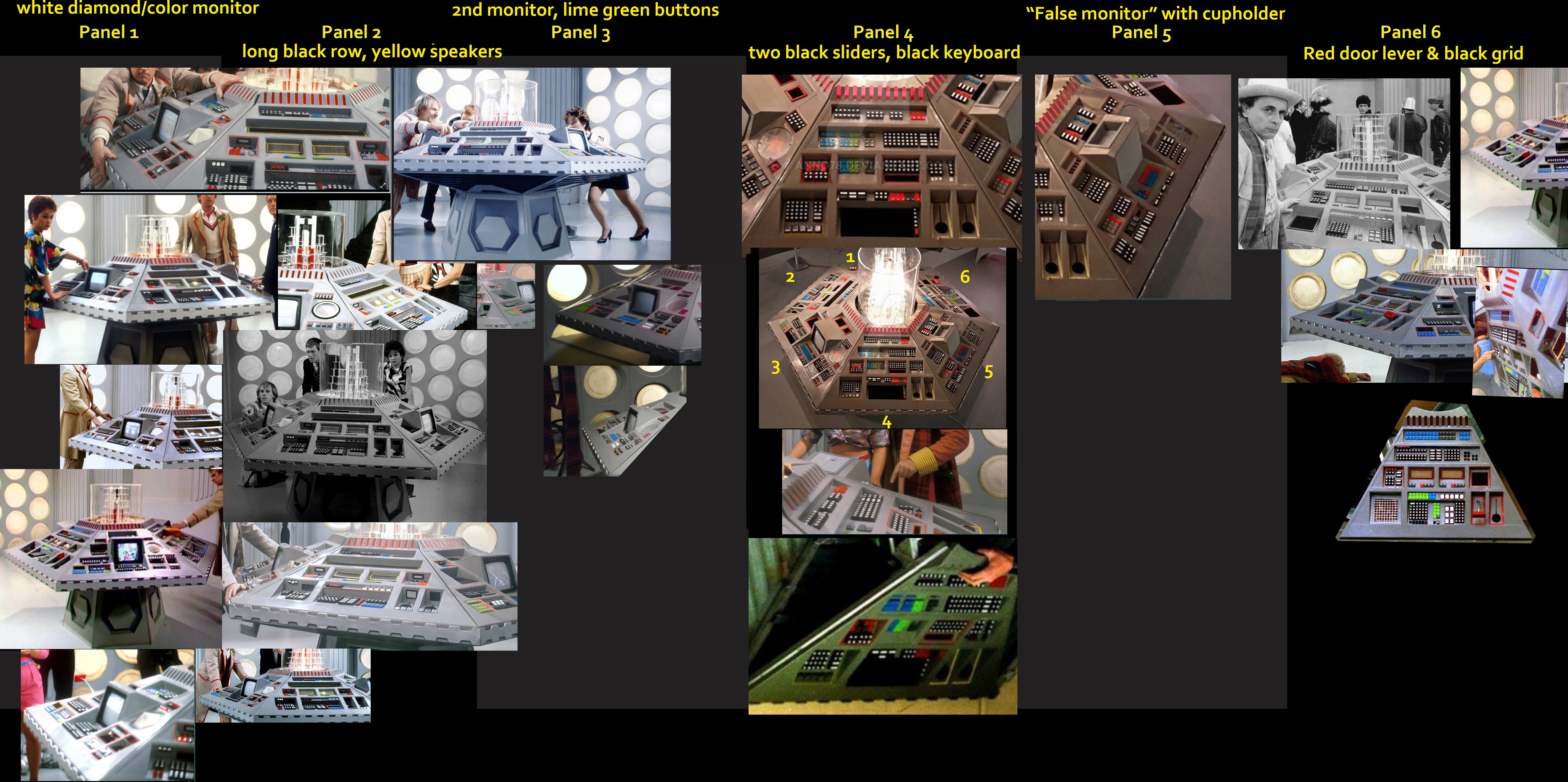
The colors below should match the general layout of the console, not counting the red grooved around the hexagonal top section.
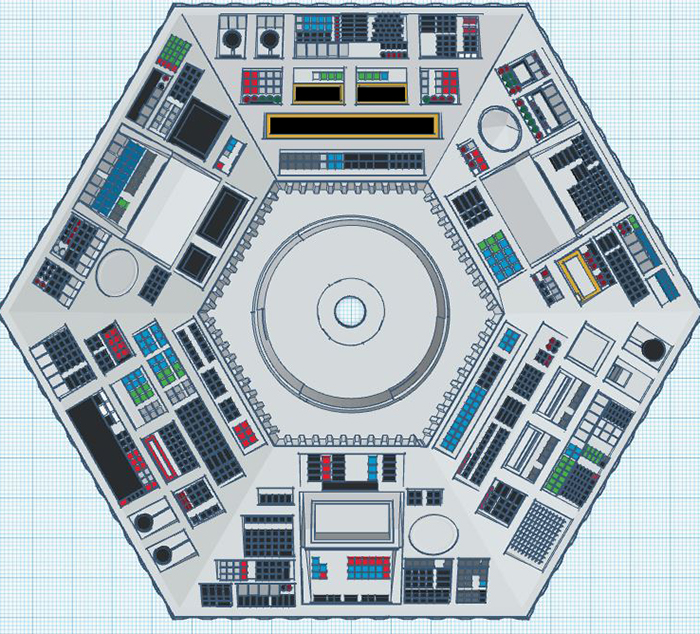
For detailed color information consult this large photo montage.
Whenever possible, I tried to use the colors seen on-screen from the earliest episode available (with the exception of Frontios, which had some weird black buttons going on for that episode only) but for some of the harder to see panels, I was forced to use the restored Doctor Who Experience version as a reference point.
While the DWE version is mostly accurate, there are a few areas where the buttons differ in color and shape, and based on photos I found online, it appears that they had two of the panels swapped for a while before someone noticed the mistake.

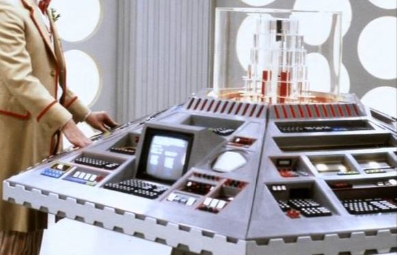
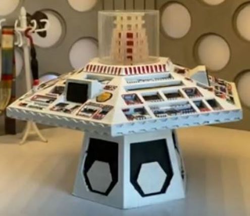
Photo courtesy of Mondas Productions. Improved version coming soon.
|
 |


